
Going Armchair Quarterback on Golden Cove’s Caches

Processor speed has rapidly outpaced advances in DRAM technology, so caching strategy is a huge part of CPU performance today. A couple of articles ago, we saw Intel’s decisions with Golden Cove’s high latency, high bandwidth cache setup. Could they have done better?
Let’s admit it – speculation is fun. So here, we’ll speculate on how Golden Cove’s performance might change with different cache configurations. To help with our analysis, we’re using ChampSim to simulate hypothetical situations. First, we set up a configuration based on Golden Cove. Then, we started changing certain parameters to see how they’d impact performance.
See the end for simulation parameters. Also remember that ChampSim uses instruction traces, not full benchmark runs. We’re only running each trace for 1 billion instructions, so they’re not representative of actual benchmark results.
L1 Data Cache
4 Cycle Latency, but only 32 KB

What if we replace Golden Cove’s 48 KB L1D with a smaller, faster one? Let’s try a 32 KB setup like Skylake’s, with 4 cycle latency. That should be completely feasible, as Skylake could clock above 5 GHz even on an inferior process. Zen 3 does so as well on TSMC’s 7nm node.
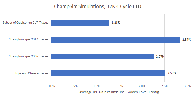
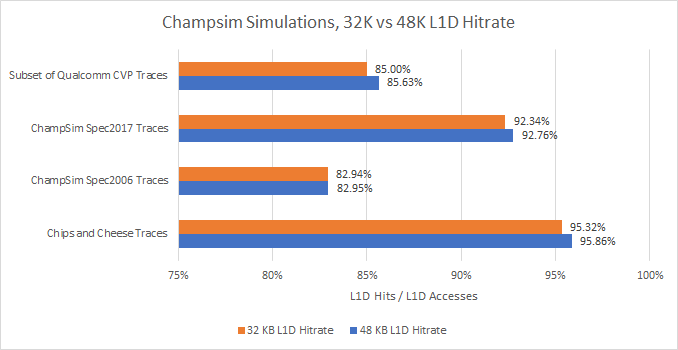
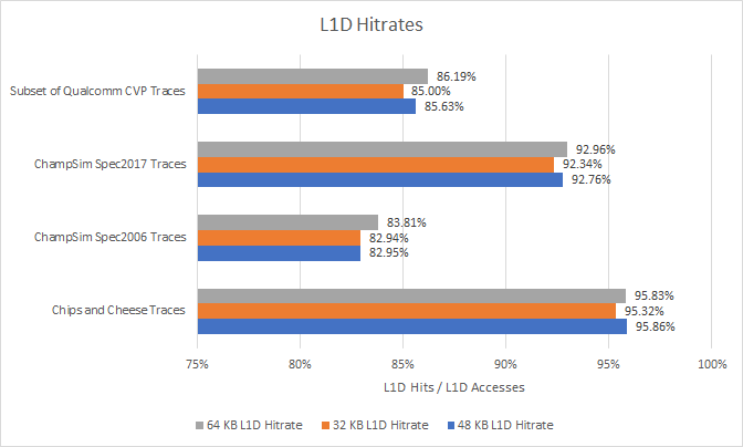
For the vast majority of traces (204 out of 214), a smaller, faster 32 KB cache won. Most memory accesses already hit a 32 KB L1 data cache, and a 1.5x capacity increase doesn’t boost hitrate by enough to offset the latency penalty:
Armchair quarterback comment: Intel should lower L1D latency, even if it means decreasing capacity and associativity.
Use Phenom’s L1D
We saw above that trading L1 data cache capacity for speed gives an overall performance win. What if we keep trading associativity (and bandwidth) to make a bigger L1D with even lower latency?

About a decade ago, AMD’s Phenom had larger and faster L1D. That wasn’t free though. Associativity was low, and the cache couldn’t handle as many accesses per cycle as modern designs. On the 45nm process, it also struggled to break 4 GHz unless overclocked pretty hard. While there’s no way to tell for sure, that L1D setup might be plausible today. Four process node shrinks could get that design working at higher clocks. Let’s give it a try.
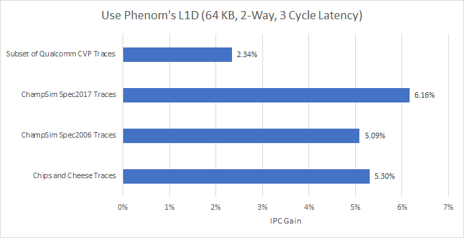
For the most part, the Phenom-like L1D performs extremely well. It wins in 207 out of 214 traces. Traces that did well with the 32 KB, 4 cycle L1D tend to do even better with this configuration. However, a few traces suffered extreme penalties:
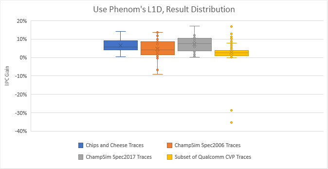
The two biggest losses showed up in Qualcomm’s traces, and unfortunately we have no clue what applications they used to generate them. In the spec2006 traces, two traces from 410.bwaves subtest showed losses of 9.18% and 6.86%. Both suffered just under a 2% hitrate decrease with the 64 KB L1D, with MPKI going from 2.03 to 3.03. But many other traces suffered lower hitrate too, so there’s something unique about those bwaves traces.
Speaking of hitrates, the 64 KB L1D failed to beat the 48 KB L1D in a surprising number of cases:
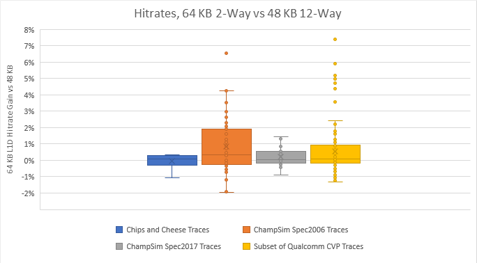
Associativity is a distinct culprit. In a 2-way associative cache, a particular memory location can only be stored in two locations within the cache. Phenom’s L1D may see fewer misses from running out of capacity, but suffers more from “hot” memory locations mapping to the same set. That throws a wrench in the works and prevents the 64 KB L1D from dominating everything.
If Intel can get a Phenom-style L1D cache to hit Golden Cove style clock speeds, they could get a serious performance win. But there are a lot of tradeoffs involved. This 64 KB cache uses 33% more data storage without providing a clear hitrate advantage. That means it’s not reducing power hungry data transfers from L2, while requiring more energy to keep its data arrays powered up. At the same time, being two way associative means each L1D lookup costs less power, because the CPU only has to compare two tags to determine whether it has a hit or miss. Golden Cove’s L1D is 12-way associative, which means 12 tag comparisons for each lookup. Finally, we have no way of knowing whether 3 cycle L1D latency is possible above 5 GHz, even on a modern process node.
Armchair Quarterback Comment: It’s not all roses, but Phenom had an exceptionally strong L1D setup. If only we could see such a cache like that today without a clock penalty…
L2 Cache
Zen style – 12 Cycle Latency, but only 512 KB
Let’s keep going for low latency, and see if it works for the L2 cache as well.

Golden Cove has a 1.2 MB L2, as does Sunny Cove in Ice Lake X and Willow Cove in Tiger Lake. Latency for this 1.2 MB cache is about 15 cycles. Intel used smaller, faster L2 caches in the past. AMD has too – all three Zen generations had 512 KB, 12 cycle L2 caches. How would a 12 cycle, 512 KB L2 compare?
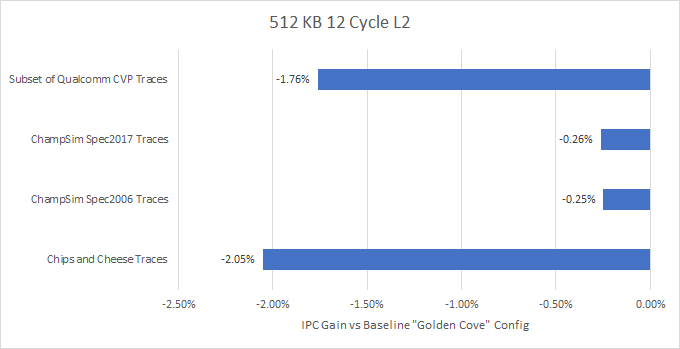
Nope. 115 out of 214 traces lose performance with the smaller, faster L2. Increasing L2 cache size by 2.5x provides such a hitrate advantage that adding three cycles of latency doesn’t matter.
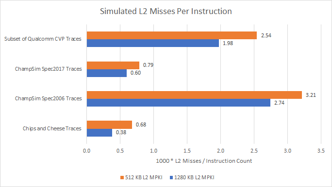
Programs access L1D a lot more than L2 (see 80%+ hitrates above), so changes to L2 latency have less impact. Also, missing L2 is more expensive on Golden Cove than on AMD’s Zen CPUs, where L3 has much lower latency. Intel absolutely made the right choice when they increased L2 size.
The result distribution is also interesting – the average above is skewed by a few outliers:
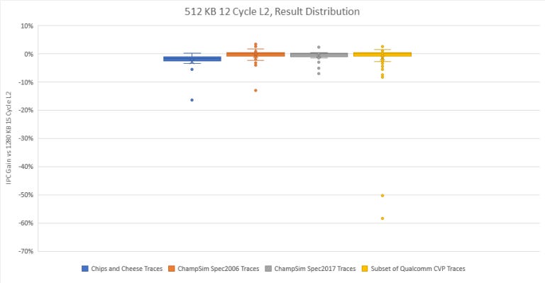
A couple of Qualcomm’s traces lose tons of performance, because L2 hitrate dropped from over 90% to somewhere in 50% range. We don’t know what Qualcomm generated those traces from. So let’s look past those and zoom in on the rest:
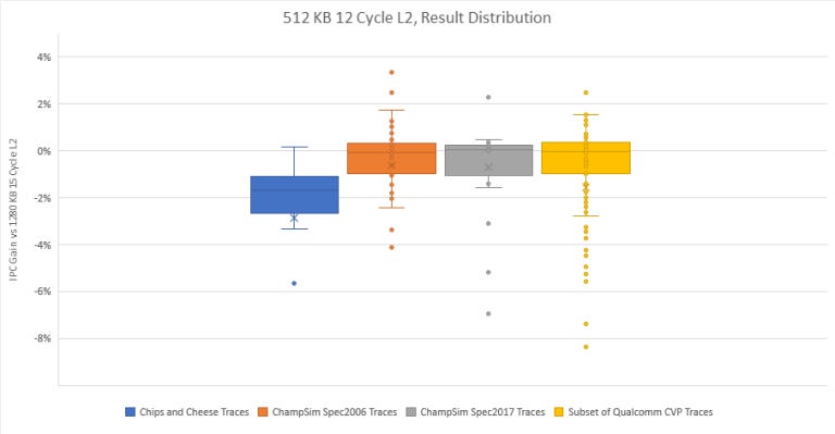
A fair number of traces end up benefiting from lower L2 latency, even if the cache is smaller. But those wins are smaller and less numerous than the losses, so it’s safe to say Golden Cove’s large L2 is a bright spot in its caching setup. Its latency is still low enough for the core to absorb the occasional L1 refill from L2. And it’s large enough to insulate the core from Alder Lake’s brutally high latency L3.
Armchair quarterback comment: Well played, Intel. Keep using those big, relatively fast L2 caches.
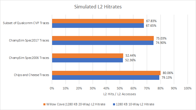
Willow Cove Style – 20 Way Associativity, 14 Cycle Latency
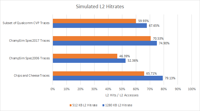
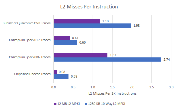
Before Golden Cove, Intel had a somewhat more capable L2 cache. Willow Cove in Tiger Lake CPUs also had a 1280 KB L2 cache, but with twice the associativity and one less cycle of latency.

As expected, we see a small IPC increase across the board. However, it’s a very small IPC increase:
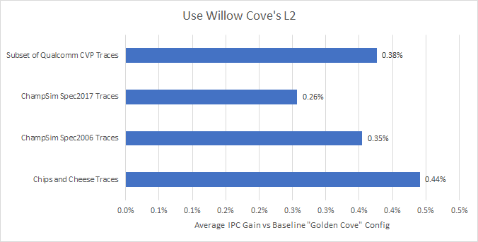
L2 hitrates barely move compared to the baseline L2 configuration. The extra associativity helps, but doesn’t seem to be worth it. A 20-way associative cache requires 20 tag comparisons for every lookup. With a small 32 KB L1 in front of it, the L2 cache is still a pretty hot structure, even if it’s not anywhere close to being accessed every cycle.
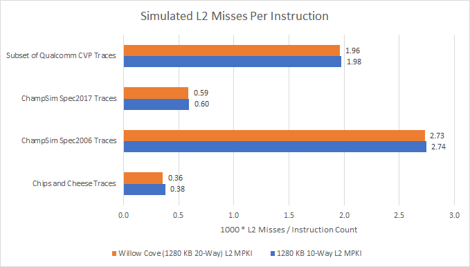
If we look at misses per instruction, we see the same picture. Increasing associativity makes more sense for the L3 cache, because it’s accessed even less often (meaning power per lookup matters less), and has much higher miss penalties. But a L2 middle level cache requires a different balance.
In isolation, Willow Cove’s 20-Way 14 cycle L2 is better. But IPC isn’t everything, because clock speed matters too. Willow Cove eventually reached 5 GHz boost clocks. Golden Cove launched with 5.2 GHz boost clocks, and is set to reach 5.5 GHz in the near future. The low IPC gains offered by Willow Cove’s L2 are more than offset by Golden Cove’s higher clocks and other architecture changes. Willow Cove’s L2 is probably a straightforward extension of Sunny Cove’s 512 KB 8-way L2, with cache ways added to reach Intel’s desired capacity. Golden Cove’s L2 is likely a better tuned version that trades a tiny bit of hitrate and latency for better clock speeds.
Armchair quarterback comment: If using Willow Cove’s L2 means a 200 MHz clock regression (or more), it’s not worth it. Intel should only use Willow Cove’s L2 instead if it’s basically free in terms of clocks and power compared to Golden Cove’s L2. That’s unlikely to be the case though.
L3 Cache
Borrow Zen 3’s L3 Design
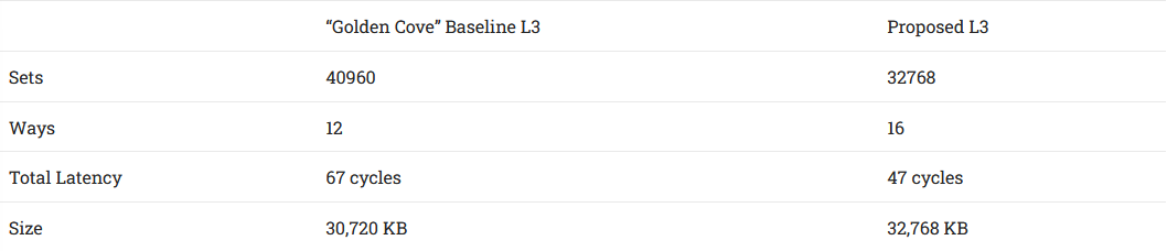
Since Zen 1, AMD has used a very fast, tightly coupled L3. Much like Sandy Bridge, Zen runs L3 at core clock, resulting in low latency. To help power efficiency, Intel abandoned this approach starting with Haswell. Intel’s iGPU shares the L3 cache, and it’s a waste of power to increase core clock just because the iGPU needs cache bandwidth for video decoding. But what if Intel chose a different path? What if they strictly focused their cache and interconnect optimizations on CPU performance?
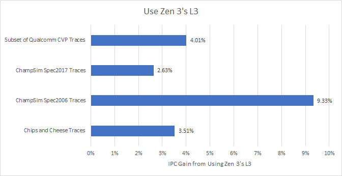
To the surprise of absolutely no one, a bigger, faster L3 with higher associativity wins everywhere. Some traces saw ridiculous gains. For example, libquantum traces from the Spec2006 set somehow saw large L3 hitrate gains even with a minor capacity increase. Other results are harder to explain. Some get large gains even though L3 hitrate barely changed, suggesting they benefit from the latency changes alone. Our trace of Geekbench 4’s HTML 5 DOM test is an obvious example. It completely fits within both L3 configurations, so its 5.51% IPC gain can be completely attributed to lower latency. But most traces seem to benefit from a mix of slightly higher hitrate and lower latency. Here’s an overview of the result distribution:
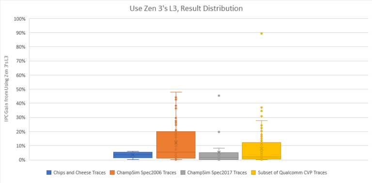
Armchair quarterback recommendation: Lower L3 latency. Consider putting the ring and L3 cache back on the core clock domain, Sandy Bridge style. That may mean dropping some power efficiency under light iGPU-only load. Or not sharing the L3 between the CPU and iGPU. But strong single-threaded performance is a traditional Intel advantage, and AMD is scary close even after Alder Lake’s release. Every little bit will matter if Intel wants to retain their traditional advantage.
VCache: Giant L3 via Stacked SRAM
Now we’re getting into crazy territory. But that’s the good thing about a simulation – we can change whatever parameters we want, without caring about realism.

AMD has been all about cache and clever packaging for the past couple years. But they weren’t always a leader. More than half a decade ago, Intel put a huge 128 MB eDRAM cache into the CPU package. It had 40-50 ns of latency (according to Anandtech’s testing) and up to 50 GB/s of bandwidth. What if Intel was a leader now? What if they used cutting edge stacking technology to triple L3 capacity with just a small latency penalty?
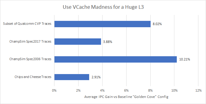
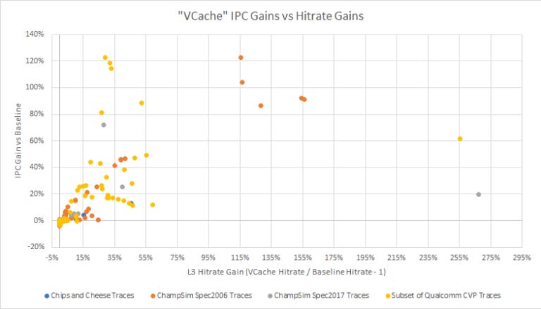
With a giant 90 MB L3 cache, we see some IPC gains on average. But the distribution shows some funny characteristics. A lot of traces don’t benefit at all or see slight IPC losses. On the other extreme, a batch of traces get completely broken by the huge L3, and see over 40% IPC gains. That drags up the average.
In the set of Spec2006 traces, leslie3d and libquantum both see gigantic gains (45% and 93% respectively). lbm from the Spec2017 traces does too (70%). Omnetpp and cactuBSSN see lower gains with around a 20% IPC lead over the baseline config. But that’s well over an average generational jump. When this crazy VCache config wins, it can win by massive margins.
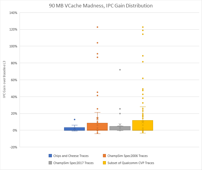
In most cases though, traces either see modest gains or modest losses from increased L3 latency. The second case is actually more common. Out of 214 traces, 111 lost IPC compared to the baseline.
Right now, pulling off a giant L3 with exotic packaging comes at high cost. AMD has only been able to announce a single desktop SKU with 3D stacking. That SKU, the 5800X3D, only has a single compute die, suggesting that TSMC’s 3D stacking tech isn’t mature enough for a bigger launch.
Armchair quarterback comment: Stacking dies to create a huge L3 cache is really cool. But performance gains vary wildly, and the required packaging technology isn’t ready for the spotlight yet. Finally, a lot of traces lose performance from higher L3 latency.
VCache is therefore a specialized solution. You really need to know what applications you’re targeting, and can’t expect to see gains across the board. Golden Cove is a general purpose CPU, so VCache doesn’t make sense for it.
Changing Several Things Up
Use Zen 3’s Caches. All of them

What if you kept Golden Cove’s width and reordering capacity, but used Zen 3’s cache hierarchy? Because all of Zen 3’s caches can run above 5 GHz, it’s technically possible. Realistically, it’s not possible due to Intel and AMD’s different design goals, so we’re firmly in fantasy land here. But it’s a simulation, and we can change the parameters as we like.
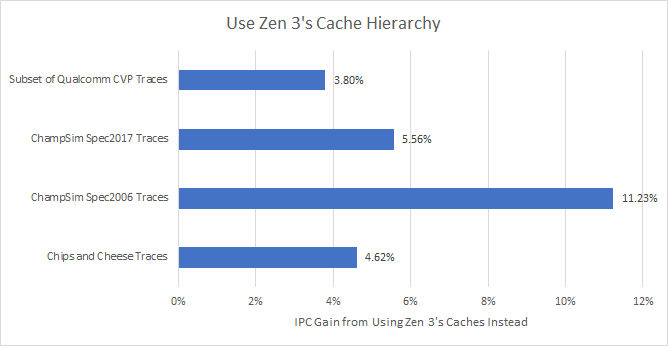
Results are complicated. We know Zen 3’s lower latency L1D and L3 do very well. We also know Golden Cove’s large L2 is better than Zen 3’s smaller but faster 512 KB one. For the most part, the former outweighs the latter, and Zen 3’s cache configuration pulls ahead. But L2 size is still important, because IPC gain correlates negatively with increase in L2 misses:
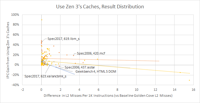
Our Geekbench 4 HTML 5 DOM trace loves Golden Cove’s large L2, and got 4.04% lower IPC with the simulated Zen 3 cache configuration. It saw just 0.79 MPKI with a 1280 KB L2, but suffered 2.33 MPKI when L2 size was reduced to 512 KB. On the other end, the SPEC2006 MCF trace appears sensitive to L3 latency. It suffers a lot of L2 misses, and bringing L2 size to 1280 KB doesn’t reduce miss rate by enough. MCF apparently does “single-depot vehicle scheduling in public mass transportation”, according to SPEC’s documentation, so I’m not sure how applicable it is to consumer workloads. ChampSim’s SPEC2017 LBM trace is an extreme example of L3 latency effects. It sees almost no change in L2 misses per instruction. Reduced L1 latency seems offset by smaller L1D size, as we saw above that using a 32 KB, 4 cycle L1D reduced IPC by 0.02%. Therefore, the over 40% IPC gain we saw for that trace can be attributed to L3 performance alone.
Armchair quarterback recommendation: If you have to choose between a bigger L2 and a lower latency L3, pick the latter. Increasing L2 cache size from 512 KB to 1280 KB sometimes produces huge hitrate increases, but is quite inconsistent. Meanwhile, a large 30 or 32 MB L3 is often enough to cover an application’s working set.
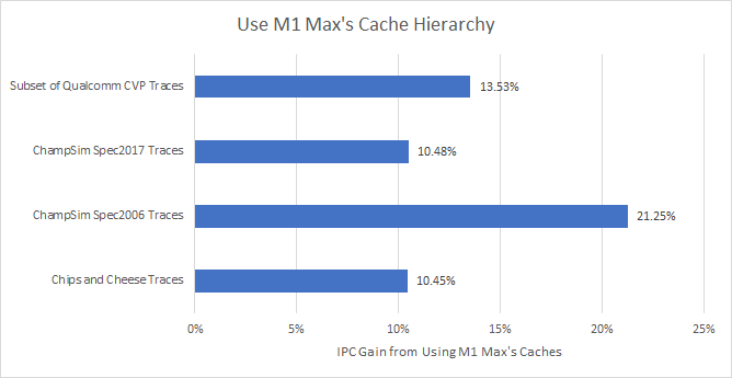
Use Apple M1 Max’s Caches
This is a completely unrealistic scenario. M1 can’t get anywhere near Golden Cove’s clock speeds. Apple and Intel’s cache setups target very different use cases. But this is a simulation and we can do crazy things.

The vast majority of traces (205/214) see gains with Apple’s latest cache hierarchy. Unlike the previous scenarios, around half the traces see larger than a 10% gain. We’re looking at a generational performance improvement off an overhauled cache hierarchy alone.
M1’s caches are exceptional. Its L1D caches have several times the capacity of those found in Intel and AMD’s latest chips. Adding the 192 KB L1i and 128 KB L1D gives 320 KB of total capacity. For perspective, Intel’s L2 caches were 256 KB all the way from Nehalem to Skylake, while AMD’s Zen generations have used 512 KB L2 caches. There’s a pretty noticeable hitrate advantage:
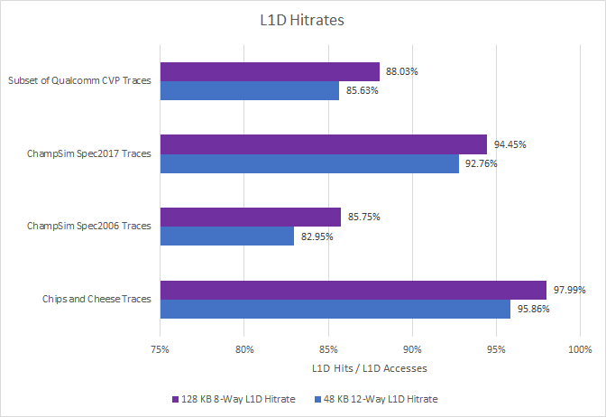
On top of that, M1’s L1D has 3 cycle latency. It’s like a better version of Phenom’s L1D. We saw earlier how much potential that had, especially with better hitrates. Apple’s design does exactly that.
M1’s cache superiority continues to L2. From Anandtech’s data, M1’s L2 cache has the latency of Gracemont’s L2, but its size is comparable to that of L3 caches in some desktop chips. From the L2 cache’s size and the system level cache’s high latency, it looks like M1’s L2 functions as a last level cache for the CPU cluster. It’s therefore not comparable to the L2 mid level cache on Golden Cove:
Apple’s 128 KB L1D and fast L2 eliminate the need for a mid level cache. Meanwhile, the L2 is large enough to insulate CPU cores from the high latency system level cache.
M1 Max’s 48 MB system level cache seems to fill the same role as eDRAM on Intel’s big iGPU SKUs, or Infinity Cache on AMD’s RDNA 2 GPUs. Because it’s placed close to the memory controller, it suffers high latency that makes it non-ideal for CPU accesses. Instead, it looks targeted towards M1 Max’s huge integrated GPU. The SLC would reduce GPU-side memory bandwidth demands, and high latency wouldn’t matter as much because GPUs are generally less latency sensitive.
Apple’s caching strategy is a remarkable example of what engineers can do with a very narrow optimization target on a cutting edge process. But Intel is after peak performance on desktop, and Golden Cove has to cover a lot more bases than Firestorm. So it uses high clocks to grab the desktop single thread performance crown. Its core-to-core interconnect has to scale to high core counts, to deliver consistent cross-core locking performance. And it has to hit lower power levels for laptops.
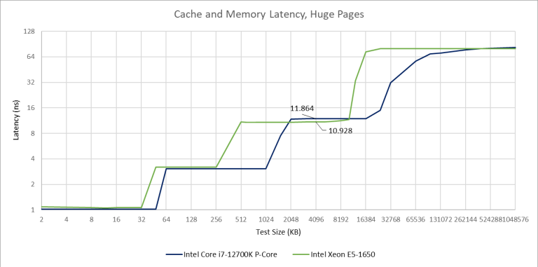
That means compromise. For example, Golden Cove’s L2 can return data in 2.94 ns. That’s 15 clock cycles at 5.2 GHz, but only 9 cycles at 3.2 GHz. But when Golden Cove runs at 3.2 GHz, it’s L2 latency will be 4.68 ns because pipeline lengths are set in stone when the microarchitecture is designed. So, making an architecture hit high clocks means it’s less optimized when running at lower clocks.
Golden Cove has to work at lower voltages too, to let it hit lower power levels at reduced clocks. That probably requires setting lower transistor threshold voltages. Again, it’s a tradeoff, because higher threshold voltages (leakier transistors) could enable faster transistion times at higher voltages.
In the end though, a Golden Cove core achieves 8.6% more performance than M1 Max, from Anandtech’s SPECint2017 scores. If Intel released a M1 Max instead of Golden Cove and landed behind AMD’s 5950X, they would not be competitive in the desktop market. Perhaps this hypothetical scenario is better suited for seeing what Intel could have done with Gracemont. That architecture targets much lower clocks, so a M1-like cache setup could give it excellent performance and power efficiency.
Armchair quarterback comment: If Intel targets power efficiency instead of peak performance, they should take a hard look at what Apple has done.
Conclusion
Cache optimization is complicated and research into the subject goes back decades. Intel’s job gets even harder because they use one core architecture to cover many use cases. With that in mind, a few cache improvements seem within reach.
The most obvious one is to lock the L3 cache back to core frequency. Intel did this with Sandy Bridge, and achieved 29-30 cycle L3 latency on their client parts. Even Sandy Bridge-E parts with more ring stops and lower clocks end up getting lower L3 latency than Alder Lake:
Sandy Bridge’s strategy does come with drawbacks. It’s less energy efficient when the iGPU is active and needs L3 bandwidth, because the cores are pushed to high frequency along with the ring bus and L3. But on desktop, power efficiency under iGPU load takes a back seat to pure CPU performance. We also can’t ignore AMD. They’ve been very competitive for the past few years, making it even more important for Intel to defend their traditional turf. A lower latency L3 could boost Intel’s CPU performance by a few percentage points. That’s significant today, because the desktop performance crown is often won by just a few percent.
Next on the viability list is going back to Skylake’s 32 KB L1 data cache, trading capacity and associativity for speed. But this might not be possible without other tradeoffs. Golden Cove can do three loads and two stores per cycle. That could be the root cause of its higher L1D latency. With latency higher already, Intel may have decided to increase capacity and associativity, because that could be handled within 5 cycles.
Other options are clearly less viable. But they do show how much cache setups can impact core performance, without any changes to the core. M1’s cache setup stands out as being particularly excellent. It provides a generational performance-per-clock gain all by itself. AMD’s caching strategy in Zen 3 is also superior to Intel’s. In terms of IPC gain, it’s not as good as M1’s. But it’s especially dangerous to Intel because it can run at similarly high clock speeds. That caching advantage lets AMD achieve similar performance with much smaller cores.
It’ll be interesting to see how Intel modifies their cache setup going forward. If they stay the course with high latency caches, their core design team will have to pull miracles to compensate.
If you like our articles and journalism and you want to support us in our endeavors then consider heading over to our Patreon or our PayPal if you want to toss a few bucks our way or if you would like to talk with the Chips and Cheese staff and the people behind the scenes then consider joining our Discord.
Simulation Setup
We tried to line up major parameters with that of Golden Cove.

Unfortunately, it’s hard to do a deep analysis with the traces we have. Most of these other traces were provided by Qualcomm for the Championship Value Prediction competition, converted for use with ChampSim. They’re obfuscated to protect strategic information, so we have no clue what they traced. Others were created by Professor Jimenez at Texas A&M University, using SPEC2006 and SPEC2017 workloads. SPEC tests come with hilariously extreme price tags that make them useless for regular consumers. They also depend on compiler settings. But at least SPEC publicly documents what their tests are based off.
We’re working on creating a set of traces with popular benchmarks and consumer applications, but its been difficult. So far, Chips and Cheese traces include 7-Zip, a few Geekebench 4 subtests, video encoding with libx264, Y-Cruncher, and Cinebench R15.